
Study of Menace FiziX Airframe.
Carbon Fiber Stress and Displacement.
Under Normal Loads
For this setup 2kg of force is applied on each corner in the motor position to represent the force of a typical racing motor (e.g. T-motor F80) at full throttle. The bottom plate is tied, as that is essentially where the battery hangs.
Displacement
This measurement is to determine the bend of flex in the arms when the motors are put to maximum thrust.
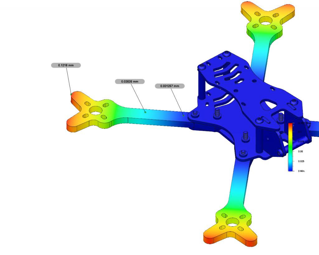
In the diagram we can see that the movement in the arm at the outmost tip moves 0.1218mm. As we move in closer to the drone body the displacement as expected is much less. This is such a small figure that it is considered negligible with absolutely no detrimental effect on the air under a throttle punch.
Stress
With the same loading on the four motor positions we can look at the stress analysis to determine potentially weak point
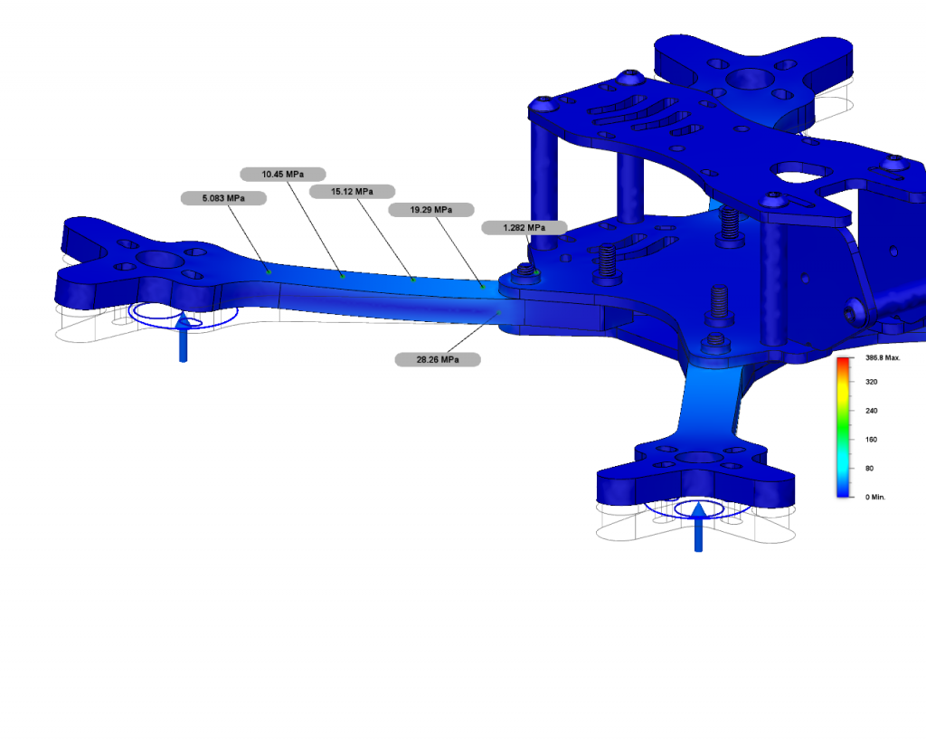
As can be seen in the stress analyses diagram the stress over the whole frame is extremely uniform.
What does this mean?
If we had weaker areas they would be highlighted as represented by the scale Red being worse case danger and a real failure point, getting better as we come down through the gradients.
So naturally we can see the stress is slightly more where the arms enter the frame body by a lighter shade of blue, this however is at such a low level and considered to be extremely acceptable.
Info… Tensile Strength of 3k Carbon fiber typically ranges from 810MPa to 1185MPa, if we take the lower figure and calculate with the highest figure from the simulation 28.26MPa we can see we are loading the arm at a really low 3.5%.
This confirms that the straight arms offer the most strength. If these were contoured for aesthetics by removing material it would create weaker areas of potential failure points.
Also as expected it can be seen from the diagram the max loading is at the point where the arm bolts to the frame.
Excessive front Loading
Determine movement of electronics in a crash.
For this setup 17822N of force is applied on the front two arms at an angle of 35degrees to represent an immense level of stress. This figure was derived by calculation of a drone weighing 0.5kg travelling at 100kph hitting a solid object. Whilst this is not an impact test it will give us an indication of how things move in the frame.
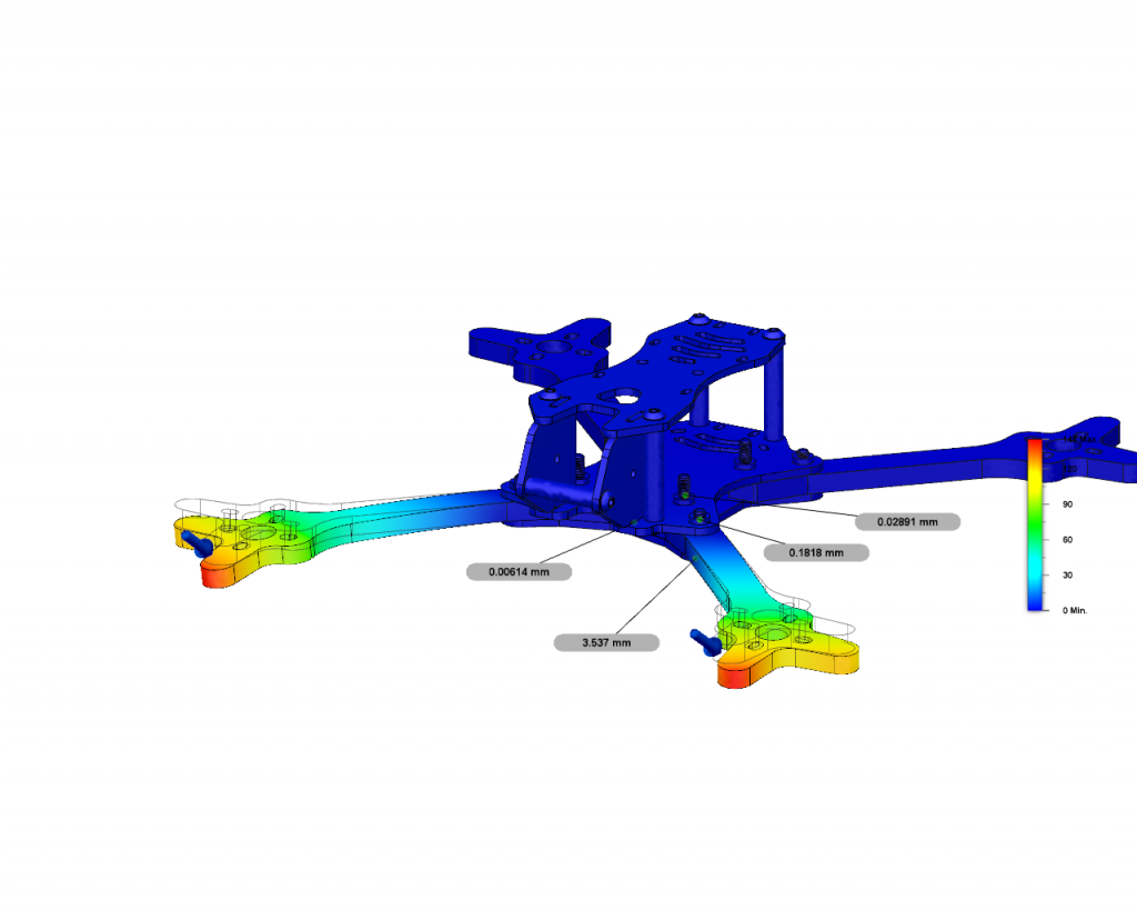
Here we can see the displacement of the arm, the part that is of interest is the two bolts that fix the arm and the inner one the stack.
The outer fixing bolt movement is 0.2mm and the inner stack bolt 0.03mm this confirms that the arrangement under these loads will not have a detrimental effect on the electronics fc stack.
We then load the front of the FPV camera cage with the same force 17822N at an angle of 35 degrees.
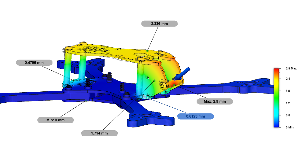
From the image we can see that the FPV cam cage horizontal bar has moved 2.9mm but notably the carbon side plates are moving proportionally with the bar, this would suggest that the camera will move back as well but as every thing moves together the camera will be protected. You can also see that the standoffs, top plate, mid plate front and back sections move. This shows how the load is spread over the frame.
Conclusion
The FiziX has performed satisfactory under normal loads and excessive front loadings. Whilst these simulations give us a very good indication of what could happen it is extremely difficult to simulated every permutation of a crash. In real life testing we have received very minor damages out of the 40 frames made up into quadcopters that have been flown and crashed repeatedly.
Charge your batteries, plug in your goggles, fly the FiziX and enjoy.
+ More Details of the FiziX click here